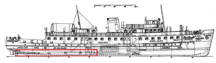
PROPELLERS & SHAFTS
Balmoral has two engines, two propeller shafts and two propellers. She
is described as a 'twin screw' ship as propellers are also called screws.
PADDLES V PROPELLERS
Early ships operating on the Bristol Channel had paddle wheels. These
are huge wheels ... with individual paddles .... on each side of the whip
and they push water behind as they turn and create thrust to push the ship
forward. They are almost as efficient as a propeller, despite what
you may read in some books, but they are a lot more complicated and
only suitable for very low speed engines. Paddles push a lot of water
slowly, so they are better for slower speeds and propellers push smaller
amounts of water much faster, so they are easier to steer and generally the
ship will have a higher top speed ( but not always ! ). Paddles were excellent for
early steam powered ships with very slow turning engines, and they can be used in shallow water as they do not stick
down below the hull and risk hitting the bottom, but they do not work very
well with a diesel engine as it turns much faster and thus needs lots of
gearing ( or an electric drive system ) to slow the final drive to a speed
that works with a paddle wheel. A paddle will typically turn 80 times in a minute
and a screw propeller might turn ten times faster.
.jpg)
.jpg)
.JPG)
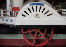
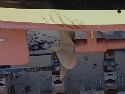
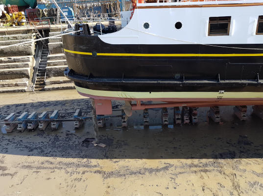
These photographs show the difference between paddles and propellers -
paddles push a lot of water slowly along the sides and propellers push less
water faster from underneath the back of the ship. They do the same job but
in a different way. Balmoral has four bladed propellers. Paddles can get
really complicated with 'feathering' floats ( the flat plate that pushes the
water ) so that they are always at 90 degrees to the water surface but the
ones shown here are basic, fixed float paddles.
Paddles may be almost as efficient, but as you will see in the engine
section, steam power is not. One of the reasons Balmoral was designed
as a propeller driven ship was to save money and also to enable her to
manoeuvre in tight spaces - and saving money, even in 1949 meant using
diesel engines. Any paddle steamer that carries passengers
must by law have the paddles linked so that they turn together, this was
after an accident on the Thames in the early 20th Century, and thus they are
difficult to turn at low speed as there is no water passing the rudders.
A propeller pushes directly on the rudder behind it and thus the ship can turn more easily. Also, by going forward with one propeller and
backwards with the other, the ship can almost turn in its own length which
can be really handy in a tight spot. A paddle steamer carrying passengers
can't do that !
Thus, if you want to operate in shallow water and can afford more crew and
more fuel, paddles are good, but if you want to operate at low cost, visit
places that are limited in turning space and want to be able to start and
stop easily, you want diesel engines and propellers. Sadly today,
paddle steamers are not used other than for historic excursions and pleasure
cruising - they just cost too much to operate !
PROPELLER SHAFTS
Propeller shafts transmit the power from the engine to the propellers at the
stern of the boat. The propeller has angled blades that literally
screw it through the water and this produces thrust that pushes the ship
along.
The shafts run half the length of the ship and are strong enough to transmit
the power of the engines at full speed. They are supported in large
bearings so that they are held exactly in line with the opening at the
back of the ship where they pass through the hull. Any misalignment would
cause very rapid wear and lead to leakage. This assembly is known as
the stern gland and is a very heavy duty waterproof bearing and seal that
keeps the water out of the ship and lets the shaft turn smoothly.
Outside the hull of the ship, the propeller shaft has a further length of
tube which also needs to be held steady or it would flex and vibrate, so
there is a large steel 'A bracket' that acts as a final bearing ( tail shaft
bearing ) and holds the end of the shaft firmly in place. Directly
behind the a bracket is the propeller. Behind the propeller is the rudder,
positioned so that water from the propeller flows past it to increase the
effect of the steering.
.JPG)
This is one of Balmoral's propeller shafts and bearings - the shaft is
about 200 mm in diameter.
The big ring on the right is a coupling - if the
shaft has to be removed this is undone and the whole shaft pulled out of the
back of the ship ...but only when it is in drydock !
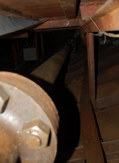
This is the shaft 'tunnel' looking forward towards the engines. It
isn't really a tunnel as the floor of the lounge forms the top and it has no
sides either!
The structure of the hull, the ribs and the actual bottom of the ship are
clearly visible.
The round thing with big bolts is a coupling to join parts of the shaft
together.
This has to be very accurately aligned so that there is no movement and
the entire shaft is in a direct line from the engine crankshaft to the
propeller . It is supported by bearings throughout its length.
As well as turning the propeller the shaft has another purpose. There is a
force of several tons on the shaft at full speed. The propeller transmits
the power of the engine to the water, but the water is pushed backwards as
the propeller blades try and move forwards. This creates a forward
pressure on the propeller and this in turn pushes on the shaft. If the
pressure is not absorbed into the structure of the ship, the whole propeller
shaft would try and move forward into the engine room, and wear out
the main engine bearings by putting a huge force on them - they are not
designed to take this ! Additionally the movement would destroy the
tail shaft bearing, stern gland and cause a major water leak !
Thus every propeller shaft has a thrust bearing assembly. This is a
large bearing that is supplied with oil to lubricate and cool it.
The outer part of the bearing is firmly attached to the hull of the ship and
this is the point at which all the power of the engine is absorbed
and where the force generated by burning fuel actually becomes the force
that moves the ship.
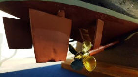
Balmoral has twin screws and twin rudders. The water moving away
from the screws when going forward passes the rudders and makes the steering
more effective.
The white blocks on the rudders are zinc anodes designed to reduce corrosion
of the steel hull.
You can see the four bladed propellers and the edge of the 'A bracket'
immediately ahead of it.
If the tail shaft bearing or stern gland fails, the ship will be unable to
move and may leak water. To make matters worse, it can't be repaired
while the ship is afloat and has to be done in a 'dry dock' .
Thus it is
essential that the stern glands are kept in very good condition.
If the
propeller shaft needs repair, it has to be removed from the ship by taking
off the rudder behind the propeller and then pulling the shaft backwards
out of the ship .
This is an
horrendous job and although the safety authorities insist that the
bearings are checked regularly, it costs a lot of money and takes a long
time.